Solution Description
Production description
Practically fifteen many years,Xihu (West Lake) Dis. has concentrated on the research and improvement, style and manufacture of cardan shafts on the rubber equipment. Our producted cardan shafts are widely used by rubber and plastic equipment company, popular for case in point, HangZhou Hua Han Plastic Machinery Co. Ltd. HangZhou Rubber & Plastics Machinery Group, HangZhou DoubleStar Rubber Machinery Co. Ltd., ZheJiang devoted machinery Co. Ltd. and other big domestic rubber equipment production enterprises.
Now it is out of the country, the merchandise are exported to Europe, North America and Southeast Asia and other locations. Designation of the universal shafts utilized in rolling device, mixer, open rubber mixing equipment. Our cardan shafts with the features these kinds of as, anti vibration, anti effect in the poor environment, anti dust corrosion, long provider lifestyle,no need to have a lot more servicing, lengthened the cardan shaft restore cycle. According to customer needs ,we can also customise the specific connection mode of common shafts with substantial coaxial, versatile joints, effortless installation, excellent following-sales services.
The pursuing desk for SWC Medium-sized Universal Shaft Parameters.
Patterns
Knowledge and Dimensions of SWCZ Collection Universal Joint Couplings
| Kind | Layout Information Product |
SWC160 | SWC180 | SWC200 | SWC225 | SWC250 | SWC265 | SWC285 | SWC315 | SWC350 | SWC390 | SWC440 | SWC490 | SWC550 | SWC620 |
| A | L | 740 | 800 | 900 | a thousand | 1060 | 1120 | 1270 | 1390 | 1520 | 1530 | 1690 | 1850 | 2060 | 2280 |
| LV | 100 | 100 | 120 | 140 | one hundred forty | one hundred forty | a hundred and forty | one hundred forty | 150 | a hundred and seventy | 190 | 190 | 240 | 250 | |
| M(kg) | 65 | 83 | a hundred and fifteen | 152 | 219 | 260 | 311 | 432 | 610 | 804 | 1122 | 1468 | 2154 | 2830 | |
| B | L | 480 | 530 | 590 | 640 | 730 | 790 | 840 | 930 | 100 | 1571 | 1130 | 1340 | 1400 | 1520 |
| M(kg) | forty four | sixty | 85 | one hundred ten | one hundred sixty | a hundred and eighty | 226 | 320 | 440 | 590 | 820 | 1090 | 1560 | 2100 | |
| C | L | 380 | 420 | 480 | five hundred | 560 | 600 | 640 | 720 | 782 | 860 | 1040 | 1080 | 1220 | 1360 |
| M(kg) | 35 | 48 | sixty six | 90 | 130 | 160 | 189 | 270 | 355 | 510 | 780 | 970 | 1330 | 1865 | |
| D | L | 520 | 580 | 620 | 690 | 760 | 810 | 860 | 970 | 1030 | 1120 | 1230 | 1360 | 1550 | 1720 |
| M(kg) | forty eight | 65 | ninety | a hundred and twenty | 173 | 220 | 250 | 355 | 485 | 665 | 920 | 1240 | 1765 | 2390 | |
| E | L | 800 | 850 | 940 | 1050 | 1120 | 1180 | 1320 | 1440 | 1550 | 1710 | 1880 | 2050 | 2310 | 2540 |
| LV | a hundred | one hundred | 120 | a hundred and forty | a hundred and forty | one hundred forty | a hundred and forty | 140 | a hundred and fifty | one hundred seventy | one hundred ninety | 190 | 240 | 250 | |
| M(kg) | 70 | ninety two | 126 | 165 | 238 | 280 | 340 | 472 | 660 | 886 | 1230 | 1625 | 2368 | 3135 | |
| Tn(kN·m) | sixteen | 22.four | 31.5 | 40 | 63 | eighty | ninety | 125 | a hundred and eighty | 250 | 355 | five hundred | 710 | 1000 | |
| TF(kN·m) | 8 | 11.two | sixteen | 20 | 31.5 | 40 | forty five | sixty three | ninety | one hundred twenty five | one hundred eighty | 250 | 355 | 500 | |
| Β(°) | fifteen | fifteen | fifteen | fifteen | fifteen | fifteen | fifteen | fifteen | fifteen | fifteen | 15 | 15 | fifteen | 15 | |
| D | a hundred and sixty | one hundred eighty | 200 | 225 | 250 | 265 | 285 | 315 | 350 | 390 | 440 | 490 | 550 | 620 | |
| Df | a hundred and sixty | a hundred and eighty | two hundred | 225 | 250 | 265 | 285 | 315 | 350 | 3690 | 440 | 490 | 550 | 620 | |
| D1 | 137 | 155 | one hundred seventy | 196 | 218 | 233 | 245 | 280 | 310 | 345 | 390 | 435 | 492 | 555 | |
| D2(H9) | a hundred | one zero five | a hundred and twenty | 135 | 150 | a hundred and sixty | 170 | 185 | 210 | 235 | 255 | 275 | 320 | 380 | |
| D3 | 108 | 114 | one hundred forty | 159 | 168 | 180 | 194 | 219 | 245 | 273 | 299 | 325 | 402 | 426 | |
| Lm | ninety five | 105 | 110 | 125 | one hundred forty | one hundred fifty | one hundred sixty | one hundred eighty | 195 | 215 | 260 | 270 | 305 | 340 | |
| K | 16 | 17 | eighteen | twenty | twenty five | 25 | 27 | 32 | 35 | forty | 42 | 47 | fifty | fifty five | |
| T | four | 5 | 5 | five | six | six | 7 | 8 | eight | eight | 10 | twelve | twelve | 12 | |
| N | eight | 8 | eight | 8 | eight | 8 | 8 | 10 | 10 | ten | 16 | 16 | sixteen | 16 | |
| D | fifteen | 17 | 17 | 17 | 19 | 19 | 21 | 23 | 23 | 25 | 28 | 31 | 31 | 38 | |
| B | twenty | 24 | 32 | 32 | forty | 40 | 40 | 40 | fifty | 70 | eighty | 90 | one hundred | a hundred | |
| G | 6. | 7. | nine. | 9. | twelve.five | twelve.5 | twelve.five | 15. | sixteen. | eighteen. | twenty. | 22.five | 22.5 | twenty five | |
| MI(Kg) | 2.fifty seven | three | three.85 | three.eighty five | 5.17 | 6 | six.75 | eight.twenty five | 10.6 | 13 | eighteen.50 | 23.75 | 29.twelve | 38.08 | |
| Dimensions | M14 | M16 | M16 | M16 | M18 | M18 | M20 | M22 | M22 | M24 | M27 | M30 | M30 | M36 | |
| Tightening torque(Nm) | 180 | 270 | 270 | 270 | 372 | 372 | 526 | 710 | 710 | 906 | 1340 | 1820 | 1820 | 3170 |
1. Notations:
L=Normal length, or compressed length for patterns with duration compensation
LV=Size compensation
M=Weight
Tn=Nominal torque(Produce torque 50% more than Tn)
TF=Fatigue torque, I. E. Permissible torque as decided according to the exhaustion toughness
Below reversing loads
β=Optimum deflection angle
MI=excess weight for every 100mm tube
2. Millimeters are utilised as measurement units besides the place noted
three. Please consult us for customizations relating to duration, size payment and
Flange connections.
(DIN or SAT etc. )
| Material: | Alloy Steel |
|---|---|
| Load: | Drive Shaft |
| Stiffness & Flexibility: | Stiffness / Rigid Axle |
| Journal Diameter Dimensional Accuracy: | IT6-IT9 |
| Axis Shape: | Straight Shaft |
| Shaft Shape: | Hollow Axis |
###
| Customization: |
Available
|
|---|
###
| Type | Design Data Item |
SWC160 | SWC180 | SWC200 | SWC225 | SWC250 | SWC265 | SWC285 | SWC315 | SWC350 | SWC390 | SWC440 | SWC490 | SWC550 | SWC620 |
| A | L | 740 | 800 | 900 | 1000 | 1060 | 1120 | 1270 | 1390 | 1520 | 1530 | 1690 | 1850 | 2060 | 2280 |
| LV | 100 | 100 | 120 | 140 | 140 | 140 | 140 | 140 | 150 | 170 | 190 | 190 | 240 | 250 | |
| M(kg) | 65 | 83 | 115 | 152 | 219 | 260 | 311 | 432 | 610 | 804 | 1122 | 1468 | 2154 | 2830 | |
| B | L | 480 | 530 | 590 | 640 | 730 | 790 | 840 | 930 | 100 | 1010 | 1130 | 1340 | 1400 | 1520 |
| M(kg) | 44 | 60 | 85 | 110 | 160 | 180 | 226 | 320 | 440 | 590 | 820 | 1090 | 1560 | 2100 | |
| C | L | 380 | 420 | 480 | 500 | 560 | 600 | 640 | 720 | 782 | 860 | 1040 | 1080 | 1220 | 1360 |
| M(kg) | 35 | 48 | 66 | 90 | 130 | 160 | 189 | 270 | 355 | 510 | 780 | 970 | 1330 | 1865 | |
| D | L | 520 | 580 | 620 | 690 | 760 | 810 | 860 | 970 | 1030 | 1120 | 1230 | 1360 | 1550 | 1720 |
| M(kg) | 48 | 65 | 90 | 120 | 173 | 220 | 250 | 355 | 485 | 665 | 920 | 1240 | 1765 | 2390 | |
| E | L | 800 | 850 | 940 | 1050 | 1120 | 1180 | 1320 | 1440 | 1550 | 1710 | 1880 | 2050 | 2310 | 2540 |
| LV | 100 | 100 | 120 | 140 | 140 | 140 | 140 | 140 | 150 | 170 | 190 | 190 | 240 | 250 | |
| M(kg) | 70 | 92 | 126 | 165 | 238 | 280 | 340 | 472 | 660 | 886 | 1230 | 1625 | 2368 | 3135 | |
| Tn(kN·m) | 16 | 22.4 | 31.5 | 40 | 63 | 80 | 90 | 125 | 180 | 250 | 355 | 500 | 710 | 1000 | |
| TF(kN·m) | 8 | 11.2 | 16 | 20 | 31.5 | 40 | 45 | 63 | 90 | 125 | 180 | 250 | 355 | 500 | |
| Β(°) | 15 | 15 | 15 | 15 | 15 | 15 | 15 | 15 | 15 | 15 | 15 | 15 | 15 | 15 | |
| D | 160 | 180 | 200 | 225 | 250 | 265 | 285 | 315 | 350 | 390 | 440 | 490 | 550 | 620 | |
| Df | 160 | 180 | 200 | 225 | 250 | 265 | 285 | 315 | 350 | 3690 | 440 | 490 | 550 | 620 | |
| D1 | 137 | 155 | 170 | 196 | 218 | 233 | 245 | 280 | 310 | 345 | 390 | 435 | 492 | 555 | |
| D2(H9) | 100 | 105 | 120 | 135 | 150 | 160 | 170 | 185 | 210 | 235 | 255 | 275 | 320 | 380 | |
| D3 | 108 | 114 | 140 | 159 | 168 | 180 | 194 | 219 | 245 | 273 | 299 | 325 | 402 | 426 | |
| Lm | 95 | 105 | 110 | 125 | 140 | 150 | 160 | 180 | 195 | 215 | 260 | 270 | 305 | 340 | |
| K | 16 | 17 | 18 | 20 | 25 | 25 | 27 | 32 | 35 | 40 | 42 | 47 | 50 | 55 | |
| T | 4 | 5 | 5 | 5 | 6 | 6 | 7 | 8 | 8 | 8 | 10 | 12 | 12 | 12 | |
| N | 8 | 8 | 8 | 8 | 8 | 8 | 8 | 10 | 10 | 10 | 16 | 16 | 16 | 16 | |
| D | 15 | 17 | 17 | 17 | 19 | 19 | 21 | 23 | 23 | 25 | 28 | 31 | 31 | 38 | |
| B | 20 | 24 | 32 | 32 | 40 | 40 | 40 | 40 | 50 | 70 | 80 | 90 | 100 | 100 | |
| G | 6.0 | 7.0 | 9.0 | 9.0 | 12.5 | 12.5 | 12.5 | 15.0 | 16.0 | 18.0 | 20.0 | 22.5 | 22.5 | 25 | |
| MI(Kg) | 2.57 | 3 | 3.85 | 3.85 | 5.17 | 6 | 6.75 | 8.25 | 10.6 | 13 | 18.50 | 23.75 | 29.12 | 38.08 | |
| Size | M14 | M16 | M16 | M16 | M18 | M18 | M20 | M22 | M22 | M24 | M27 | M30 | M30 | M36 | |
| Tightening torque(Nm) | 180 | 270 | 270 | 270 | 372 | 372 | 526 | 710 | 710 | 906 | 1340 | 1820 | 1820 | 3170 |
What Is a PTO Shaft?
A PTO shaft is a component that is important for a power take-off (PTO) tractor. There are many different kinds of PTOs, including Italian, German, and North American types. The types are categorized into different series, which will have different features such as bearing diameter, cap-to-cap length, and snap rings.
Power Take-Off (PTO) shaft
A PTO shaft is a high-speed working shaft that provides torque and lift. This is an advantage for machines that lift and lower loads and are often used on construction sites. Often, the operating elements are located outside of the operator’s cabin. A safety system is also present that allows the PTO shaft to automatically disengage if it is not turned on.
A safety retaining band 12 is used to secure the PTO shaft. The retaining band extends axially from the PTO shaft S and includes a hinge. The band may be adjustable in width to ensure a correct clearance from the PTO shaft. If necessary, it may also be secured with a conventional over-center clamp.
The power-take-off (PTO) shaft is a crucial part of a tractor. Understanding how power is transferred from the tractor’s engine to the implement requires a better understanding of how this shaft works. The torque and speed of the PTO shaft is essential to developing and utilizing the power of the tractor. There are many ways to measure torque and speed at the PTO shaft, including using a telemetry or encoder system.
A Power Take-Off (PTO) shaft safety retainer is an inexpensive, dependable, and fully effective device that protects the PTO shaft from entanglement. Its effectiveness will become clear after reading the specification. A power take-off shaft safety retainer is not difficult to install and is a good choice for many applications.
PTO shafts have a dangerous tendency to separate from the driven machinery. This poses a safety hazard because the PTO shaft can continue to whip around while the operator is driving the machine. Additionally, it can be very difficult for the operator to reach the power plant when operating PTO-driven equipment.
Safety chain
The safety chain on your PTO shaft is an important component of your tractor’s safety system. A properly guarded PTO can prevent entanglement with people, tools, and objects. Moreover, it reduces the risk of the PTO shaft becoming detached from the tractor. It also prevents people from stepping over the rotating shaft.
When not guarded, a PTO shaft is extremely dangerous. It can cause serious injuries and even death. Proper safety chains can prevent this from happening and protect livestock from damage to the PTO shaft. If you’re looking to purchase a safety chain for your PTO shaft, be sure to get one that fits tightly.
When properly attached, a safety chain can keep the shaft from swinging when the PTO is engaged. A 540-rpm PTO shaft will make more than two complete revolutions in less than five seconds. That means it can wrap someone in five tenths of a second. And if you try to pull away, you’ll get wrapped even tighter!
Another reason to use a safety chain is to prevent injury from clothing getting caught in the drive shaft. A jacket or a sweater can entangle itself around the PTO shaft and cause a serious injury. The clothing can also trap the injured limb against the shaft. Hence, the chain should be removed as soon as possible after the operation is completed.
A safety chain is an essential part of your tractor’s safety system. It prevents an accident from happening because of improper maintenance. A poorly maintained PTO shaft can result in severe injuries or even death. Properly installed and maintained safety chain can help you prevent any kind of PTO shaft accident.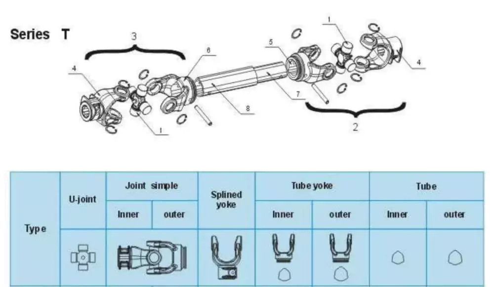
Universal joint
A bad universal joint can cause a number of problems for your tractor or implement. These issues may include squeaking or clunking noises when you shift gears, or a shuddering sensation when you brake. If you notice any of these symptoms, it is best to take your vehicle to a mechanic right away for a thorough inspection. If not fixed properly, a bad universal joint can separate from the drive shaft and cause major damage to the tractor or implement.
In order to choose the proper universal joint, you must consider the size of your PTO shaft. Some implements have a diameter of 14 inches or more from the hitch point to the end of the input shaft. The longer distance helps prevent the PTO shaft from bottoming out when making sharp turns. It also prevents the two parts of the shaft from detaching during cornering.
Universal joints are used in agricultural and forestry equipment and other vehicles with large number of rotors. They can be made of different materials. The most common is steel or stainless steel. This material can last for many years. A universal joint is an excellent option for small tractors, lawn mowers, and other agricultural equipment.
The universal joint is also very useful when coupling or extending drive lines. It comes with 2 yokes and a cross kit. The yokes measure 6 x 13/8″ spline, while the cross kit measures 30,2 x 92 mm. The universal joint is made to withstand extreme temperatures. It can be easily disassembled and serviced if necessary.
Square rigid shaft
Torsion is a property of a mechanical system that is affected by changes in torsional rigidity. Torsional rigidity is measured as the torque needed to twist one unit of angular measurement over one unit of length. A shaft with high torsional rigidity will provide a stable mechanical interface.
Different shafts may have different types of collars. The most basic one is a sleeve, which is composed of a thick tube with the same diameter as the shaft. The sleeve is attached to each end of the shaft and has threaded inserts to prevent longitudinal movement.
The PTO shaft also has a safety shield on both ends. It helps to prevent accidents by securing equipment to the tractor. It can be found in domestic and metric shapes. The domestic versions are generally round and domestic shaped, while metric versions are available in a bell, football, star, and metric shape.
An CZPT coupling consists of three pieces: a center plastic disc, two encompassing discs, and a flange. These parts are joined together with a ring that is screwed to the shaft. Some couplings feature oil injection points on the coupling. These can supply oil under pressure to the coupling’s annular grooves. This helps it ‘float’ and aids in the removal.
Another type of flexible coupling is the universal joint. These couplings can be made from a variety of materials, such as rubber, braided metal wire, or woven wire. They can be fabricated to withstand various misalignments. But, unlike rigid couplings, flexible couplings are susceptible to shock and vibration.
Economy PTO
Economy PTO shafts are designed to reduce the overall torque and power consumption of a tractor. They can be manually adjusted to engage and disengage the PTO. The cab mounted control/monitoring unit 14 has a switch 19 that selects between the economy and normal driving modes of the PTO. Using the economy mode decreases the engine rpm while using a lower gear ratio to drive the PTO shaft.
Economy PTO shafts come in hydraulic and mechanical versions. Both types are suitable for agricultural tractors. They allow the tractor to operate at a lower rpm, which reduces noise and vibration. They can also be used in a wide range of equipment. The transmission PTO is the oldest type, and is directly connected to the transmission. When the clutch is engaged, it drives the transmission.
Standard PTO shafts are available in various diameters, splines, and speeds. Many implements are designed to be compatible with one or more of these types of PTO shafts. The domestic versions come with a splined front shaft and a square, rectangle, or round secondary shaft.
Another difference between the two types is the number of teeth on the toothed wheel. The economy PTO allows the tractor to run at a lower rpm than the standard PTO. The engine rpm can go as low as 1600 while using the economy PTO. It also helps to reduce noise and vibration in the cab.
The present invention solves these issues and provides an increased level of automation and operator awareness of the PTO function. It also includes a system for detecting the type of PTO shaft and automatically setting the parameters of the control routine.

editor by czh 2022-12-19